***** Please Don't Forget To Visit These Web Comics *****

BugPudding Webcomic Adventures of Lewis and Cluck Webcomic

Additionally, You Can Help Support Cartooning in ToonBoom By Making A $5 donation.

Tuesday, September 11, 2007

Creating Multiple Shots In A Single Scene

This tutorial is focused on using Toon Boom Studio to make a cartoon short. It is intended to provide an overview of some of the steps in creating a one scene short that is composed of several view point changes more technically referred to as "shots".

Note: you can click on any image to view a larger version

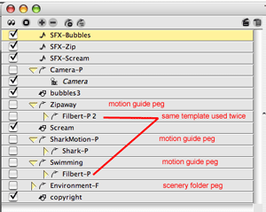
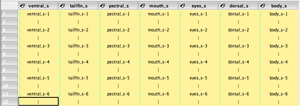
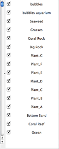
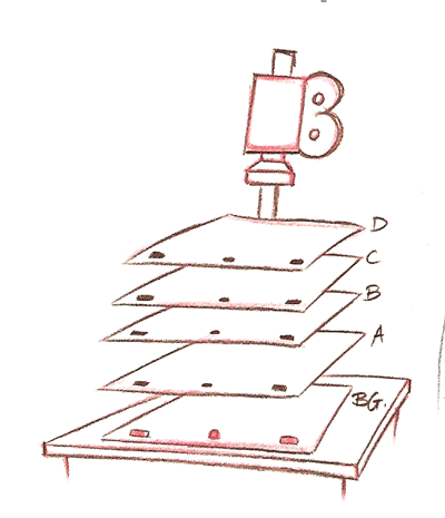
In making this cartoon short, titled "A Matter of Artistic Differences", once the concept was determined and visualized in a rough storyboard, the first step was to create the sound track and the drawing elements. As you can see from the picture of the scene's exposure sheet in figure 2 below, there were 3 sound track elements and 26 drawing elements utilized. Now before you panic about the number of drawing elements used, only about 7 of these drawing elements contained more than one or two actual cells. Most are just occupied by a single drawing and only the main character elements have numerous drawings. The sound track was split up into three elements due to the need for overlapping of sounds in two places along the time line.

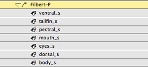
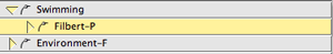
Note:
Normally we name elements as a single letter: a,b,c,d,e,.... and put the descriptions in element notes, but for this "how to" example we used more descriptive names for clarity.


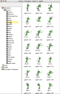
Figure 1: the library view of "agile4" drawing element cells


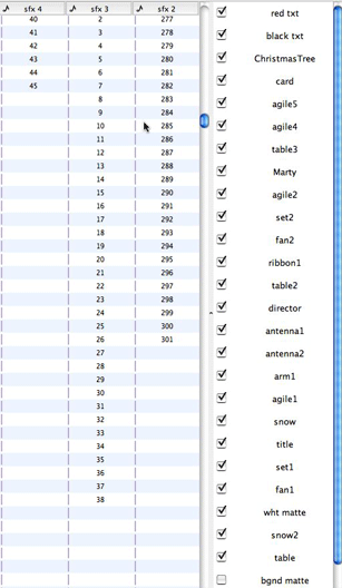
Figure 2: the scene's exposure sheet

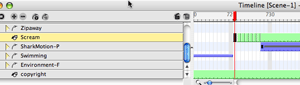
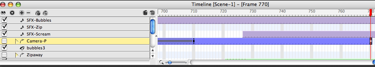
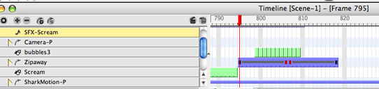
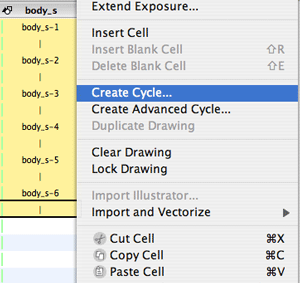
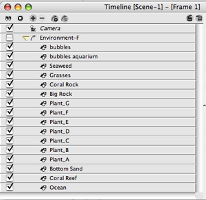
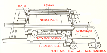
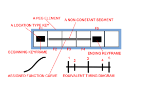
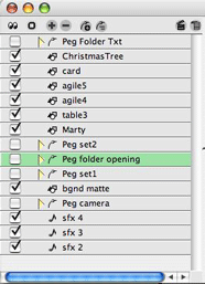
Although some of the picture composition was done using the "auto light table" to view cells across an exposure sheet frame, we normally do most picture composition in camera view. So we end up doing a great deal of the production work in the time line once the drawn cells are created. We try to avoid doing any drawing in camera view, all drawing is done in drawing view and camera view is where we composite the final scenes. As you can see by figure 3, the time line track list gets quite long. So we use peg elements like file folders to group and manage the clutter.


Figure 3: uncluttered track list with collapsed peg folders

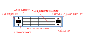
As a note of interest, because we are using TBS V3.5 or higher, there are almost no separate peg elements being used which greatly reduces the number of time line tracks. Most of the separate pegs elements we used were as grouping devices like file folders just to be better organized. Most keyed frame work is done using animated drawing elements which now include their own integrated peg. Figure 4 below shows the expanded view of the track list.


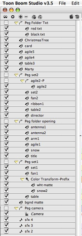
Figure 4: the final expanded time line track list

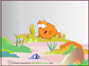
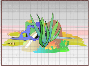
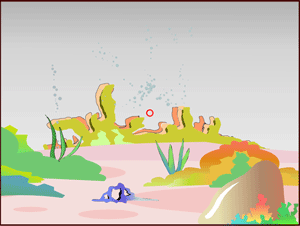
This cartoon is shot as one actual scene. The opening sequence simulates the "on screen" presentation of our character Agile Ant as he is being blown about in a snow storm on a mountain top. When Agile yells "cut, cut, cut!" out of total frustration, we see via a "pull back and pan" of the camera, that this is in fact a movie set. Then as Agile begins his angry determined walk across the sound stage, we cut to a wide shot that reveals that this is a table top set much like one that would be used in a "stop frame" puppet cartoon like Wallace and Gromit. Figure 5 shows the camera's view point framing the opening shot.


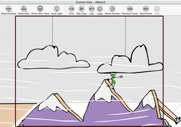
Figure 5: the opening sequence shot

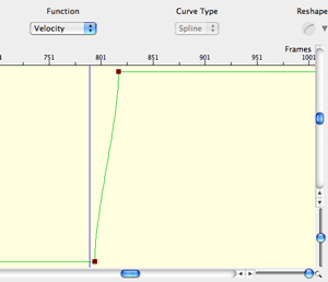
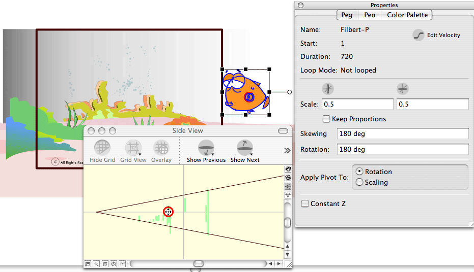
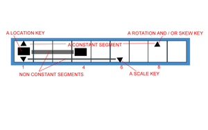
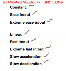
The second camera shot for our short is a "pull back and pan" reveal of the "real world" of the cartoon movie set. It is all done with the TBS camera. The initial art work was scaled only once as we set it up for the opening sequence. (see figure 8 below) The camera, which is attached to a peg element, is positioned to give us the tight shot of the mountain top with Agile blowing in the wind. Then when we are ready to make our pull back and pan move, we first set a key frame of the camera's attributes at time line frame 240. This is done to lock down the start of our camera for a motion tween. So having set the starting position of our camera move at frame 240, we move to the ending frame for this shot which we determined we wanted to be frame 356. With the transform scene planning tool selected, we move the red time line frame marker to frame 356 and use the up and down arrow keys and the left and right arrow keys of our keyboard to reposition the camera viewport to the desired ending position for our move. We also use the Top View panel to move the camera back away from the picture plane. This sets our ending keyed frame attributes. Now all that is needed is to go back to frame 240 on our camera peg and set the constant segment to non-constant and we have our camera move. We normally work with constant segments as a default setting and then we can switch the desired segment between key frames to non-constant as desired. We can adjust the velocity of the camera move using a customized function curve, but for this move we stayed with the default linear curve.


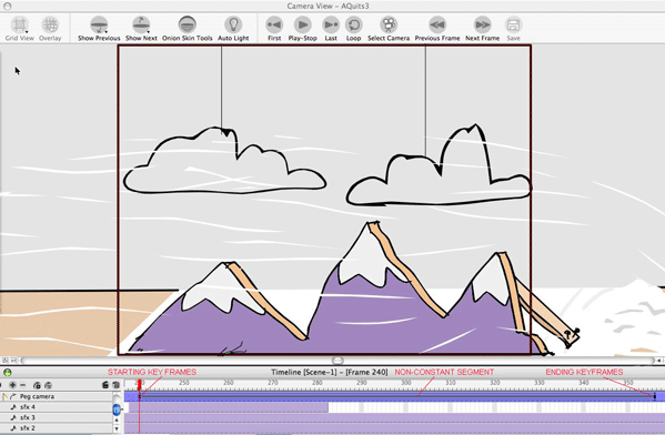
Figure 6: the time line at the beginning of the "Pull Back and Pan" shot


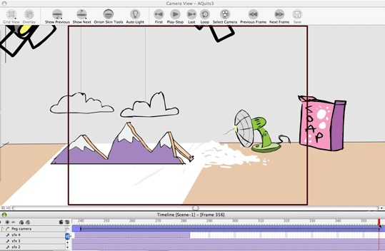
Figure 7: the time line at the end of the "Pull Back and Pan" shot


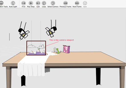
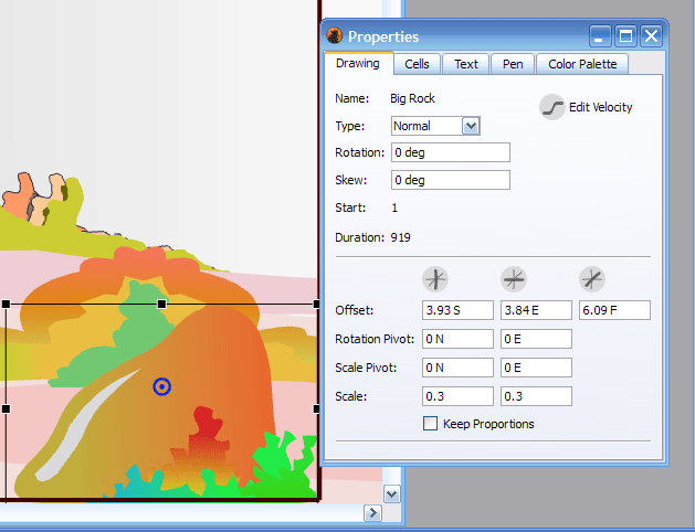
Figure 8: the relative size of the art work VS the camera viewport frame

Now comes a more complex shot sequence as we pick up Agile Ant in his determined walk across the set, first in a normal long shot, then in a really distant wide shot that reveals the true scope of our movie set and then in a closer tracking shot as he approaches the target of his wrath, that "prince" of a cartoon director, Marty.


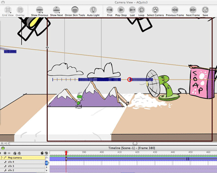
Figure 9: the first shot of Agile walking

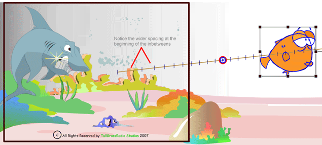
This shot sequence is made in three parts, but don't think of it as three separate sections of art work. It is one set of art work with three camera set ups. The actual character walking is a cycle that is key framed to move across the table top set. All the set and props have been scaled together as a composite picture and the character is scaled to match the same relative size as the props and set. The changes in viewpoint are all done with the camera set ups. So before we do the camera work we will animate Agile's entire walk across the whole set completely as if there were not going to be any changes in camera position. Once that's done it is all about using the TBS camera. For the first part of the sequence we position the camera viewport and create a motion tweened shot between frames 380 and 448. This is done in a similar manner to the way we did the pull back and pan including using the Top View panel to help us move the camera back farther from the picture plane.


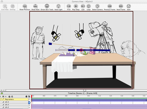
Figure 10: the wide shot of Agile walking

At frame 449 we begin the wide shot part of the sequence (figure 10). The first thing we have to do at frame 449 is reposition the camera. We have the camera positioned at frame 448 with the ending keyframe of our prior move. So at 449 we completely reposition the camera using the Top View panel again to move the camera back from the picture plane to give us the complete view of the set. Once we get the right camera set up, we add a keyframe at frame 449 to lock down our starting camera position. This wide shot lasts until frame 552 where we have made a slight adjustment of the camera to give us a really small pan during our wide shot. The shot is created by key framing the camera start position at 449 then moving the camera at frame 552 and key framing that ending position and then creating a non-constant segment between 449 and 552. The walk and the art work are never changed.


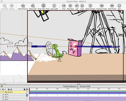
Figure 11: back to the closer tracking shot of Agile walking

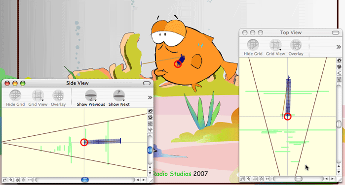
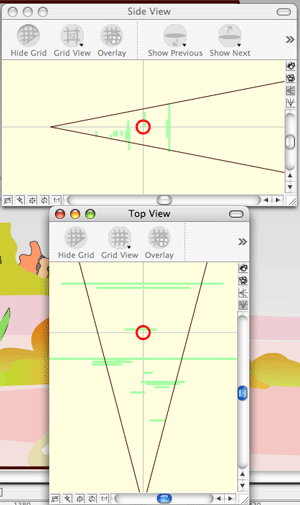
The last part of this sequence is the close tracking shot (figure 11). It starts at frame 553. So once again we need to start by making the beginning camera position for this shot and keyframe it at 553. The ending of the shot is at 777 with Agile right in front of Marty's face. Again we used the Top View panel to adjust our camera's distance from the picture plane to get the desired viewpoint. We haven't needed to use the Side View panel because although we are changing our cameras distance from the picture plane we are staying at the same horizontal eye level.


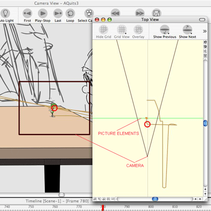
Figure 12: the last camera set up of this cartoon scene

At frame 780 we are ready for the final shot of the cartoon which is focused in on Agile as he delivers his frustrated speech to Marty. Figure 12 shows the camera viewport for this shot and the Top View panel where we are adjusting the distance between the camera and the picture plane.

As you hopefully are beginning to see, making a cartoon sequence in Toon Boom Studio is a combination of drawing and composition and cinematography. It is easy to design and produce multiple shots with in a single scene. It just takes a bit of planning up front.


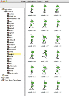
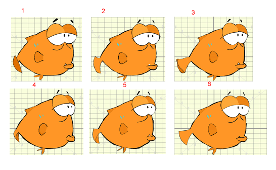
Figure 13: cells from the "agile1" drawing element


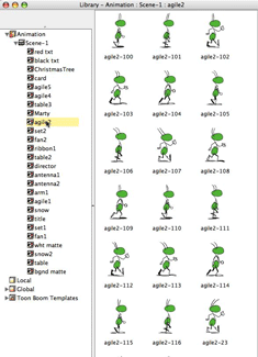
Figure 14: cells from the "agile2" drawing element

I am always glad to answer questions about making cartoons and about using Toon Boom Studio and I actively frequent the TBS User Forums. -JK

Re-watch the cartoon : A Matter of Artistic Differences

Note: This blog post is an updated version of an article which I originally wrote and published as part of our web site's TBS FAQ section which we are slowly phasing out and replacing with this blog and the Cartooning in Toon Boom WIKI.

Labels: , ,

Tuesday, June 5, 2007

Key Framed Animation Part 5

Please be sure to review Key Framed Animation – Part 1 and Key Framed Animation – Part 2 and Key Framed Animation - Part 3 and Key Framed Animation - Part 4 before you continue with this final part of this series. You can also review the demonstration scene .


In Part 3 we constructed the underwater environment for our demonstration scene. In Part 4 we created the swimming cycle for our fish and we animated his swimming into the scene using a motion guide. The storyline calls for Filbert, the fish, to tread water briefly after he reaches mid-scene before he reacts to seeing the shark. To accentuate the surprise factor of this scene we have determined in the storyboards that animating the camera is appropriate at this time. In a cinematic scene we may stay within a common setting but the use of multiple shots or view points is useful in adding to the storytelling. We are going to move in close on Filbert before he reacts and then after his reaction fills the screen, we will “hard cut” back to a reveal shot of the source of his panic.


In order to animate the camera we need to attach the camera element to a peg element, the easiest way to do that is to use the “add parent peg” icon at the top of the timeline track label list while we have the camera element’s track selected. Once the camera is attached to a parent peg, which is named Camera-P a standard naming convention for a single element parent peg, we need to go to frame 1 of Camera -P and make the transform tool active and set our initializing keyframe. This is to lock down our starting characteristics for the camera. It is always a good practice to set a transform group of keyframes on the first frame of any peg to initialize the peg. This is true for separate peg elements or integrated pegs on image or drawing elements. Next we will move to frame 671 on the Camera-P peg and add a second key frame being sure the transform tool is still active. Again prior to starting a camera move it is advised to lock down the end of any previous shot. We will start out trucking in shot on frame 672. We need to make the motion tool active and set a motion keyframe. The camera’s point of view at frame 672 is the beginning of our trucking shot.


(click on to enlarge)

Next we need to move to the ending frame of the shot at frame 710. With the motion tool still active we need to set a key frame. Now we can execute the shot by selecting the end of the motion path at frame 710 and dragging it to position our camera view point to the ending view of this shot. I usually do this in Top view first while visually watching the view point change in Camera view. I may, and usually do, make additional adjustments by dragging the end of the motion guide in the Side view as well.


Now that I have "trucked in" to the ending position of this shot, I need to go back to frame 672, the beginning position and on the Camera-P peg, I want to set the segment between frames 672’s motion key and frame 710’s motion key to be a non-constant segment. I set my TBS preferences to always create constant segments on my pegs as I prefer to set my non-constant segments manually when needed. Be sure you still have the motion tool active when setting this segment to tell TBS you are setting a motion key segment. The solid line between the motion keyframes indicates the segment is now a non-constant segment.


(click on to enlarge)

Below you can see the motion paths with their corresponding spacing indicated in both the Side and Top view panels. I left the velocity function as the default even spacing because this is a really short duration move and it works well that way. Had it been a longer move I probably would have used an ease-in ease-out velocity function.


(click on to enlarge)

Filbert's screaming reaction starts at frame 723. I animated this similarly to the way I animated his swimming cycle in drawing view by drawing the various cells to create the scream. So now I just need to insert that element and these cells into the timeline starting with frame 723. I need to be sure to have the select tool active before I start trying to position this Filbert screaming element. The hardest part of keyframe animation is making sure you always have the best tool selected for what you are trying to do. You have to be paying attention to your active tool or you can make inadvertent mistakes really easily.


The shark is also animated as an element in drawing view and I have placed his swimming cycle into the time line but he is currently off camera because we are still "trucked" in tight on Filbert.


At frame 770 on the Camera-P peg I want to set a new motion key, so I have to make the motion tool active. I add a keyframe and reposition the camera’s view point to the "reveal" of the shark. I want this camera shot to be a “hard cut” so I will leave the segment between frame 710’s motion key and frame 770’s motion key as a constant segment.


(click on to enlarge)

This causes the shot to “snap” from the "trucked in" close up to the reveal shot when the movie reaches frame 770


Now it is time to have Filbert make a strategic retreat. Actually he is going to “zip” out of there for his life!! Things will happen so fast that I can save myself a lot of work by just reusing the same swim cycle I used earlier in the scene. I made it a template, so reusing it is just a matter or dragging and dropping it from my library to the timeline.

It is just one 12 frame cycle. Now you might be wondering why I used a second instance of the swimming template rather than adding to the time line of the first instance I used at the beginning of the scene. That instance has static values I applied to it to position and flip the fish. If I just advance the timeline for that instance and repositioned Filbert with the scene planning select tool so that he was facing the opposite direction it would be a global change and mess up the first bit of animation I made. It is just cleaner and easier to reuse the template as a new series of tracks just for this short “zip” off.


So, I place Filbert swimming into the scene starting at frame 795. I use the select tool to scale him to 50% but I don’t need to flip him horizontally this time. Using the transform tool I put a starting and ending keyframe on his main character peg just for good measure and I selected the 12 frames with the main character peg collapsed and copied them. I moved to the end of the cycle and pasted them using “paste special” to extend the exposure of the first cycle to a second cycle. This second cycle will totally never be seen but I wanted the extra frames to help with my “zip” motion. Now I will attach the second instance of Filbert swimming to a peg element which I added and named “Zipaway”. This is going to be my motion guide. I collapse the Zipaway peg and make the motion tool active and go to frame 795 on the Zipaway peg and set a motion key. I then move to frame 819 on the Zipaway peg and set a second motion key. I move the motion guide's end to position Filbert off screen using the Top view and Side view to get the desired location. Then I return to frame 795 on the Zipaway peg and with the motion tool active, set the segment between these two motion keys to be a non-constant segment.


(click on to enlarge)

I want the spacing for this "zip" action to be different from the default even spacing, so I need to create a different velocity curve from the default linear velocity curve.


With the “Zipaway” peg selected in the timeline, I open the function editor; I have the function editor set up as keyboard short cut key “J” which makes opening and closing the panel really convenient. I first need to select "velocity" as my function because this is a motion segment. If it had been a scale segment I would have chosen H-scale or V-scale, for a rotation segment I would have chosen Rotation, and for a skew segment I would have chosen Skewing. They are all used to set the spacing for the “tweening” just for different attribute types. I zoom in on my frames for this segment and using the "reshape" pull down at the top right corner of the function editor window, I chose a fast out/in curve shape. I’m not interested in the end of the motion’s spacing because it will be off camera, but the beginning spacing is important to getting the desired action. I want the in betweens to be farther apart as the beginning to add speed to the action.


(click on to enlarge)

I added a special effect with bubbles in element " Bubbles 3" to give the "zip" an extra impact as Filbert is really stirring up the water as he makes for cover. That’s pretty much it for this scene. I certainly hope that this series on Key Framed Animation has given you a sound foundation on keyframing and how to use this technique in animating. There are plenty of additional aspects to key framed animation but those are for future articles.


Above is a view of the track label list with pegs mostly collapsed but I wanted to show you the tracks that were the same template reused twice as well as the motion guide peg elements.

Labels: , , , ,

Tuesday, May 29, 2007

Key Framed Animation Part 4

Please be sure to review Key Framed Animation – Part 1 and Key Framed Animation – Part 2 and Key Framed Animation - Part 3 before you continue with these next parts of this series.

In Part 3 of this series we viewed an Example Scene and began discussing the steps to creating that scene. We saw the use of the scene planning select tool in the assembly of the underwater background environment. The scene planning select tool is used to place elements into the scene initially. We reviewed some examples and discussed reasons for being careful not to use the select tool after you start key frame animation of an element or element hierarchy.

Now that we have assembled the background environment for this scene we are ready to start the character animation. The scene’s storyline calls for Filbert, a fish, to swim into the scene from off camera and to slowly swim to about the middle of the scene where he will react to meeting a ferocious shark. To accomplish this we will need a swimming cycle that will be repeated for some period of time as well as a motion path to move Filbert along as he swims.


Fig 1. The 6 keys for the swim cycle (click to enlarge)

I animated the swimming cycle through drawn images. The cycle uses only six unique images spaced on 2’s, which means one new image every other frame. A complete cycle is 12 frames in length. I constructed Filbert swimming using 7 individual elements or layers. I could easily have done it by just drawing the six key drawings on six cells of a single layer. I chose to use 7 elements to show the compositing of multiple layers to create a character. But it was totally an arbitrary choice for demonstration purposes.


Fig 2. The 7 element parts of Filbert in the Exposure Sheet

Once the swim cycle is created, I have to look at the storyboard and the director’s notes to learn the duration of the swimming prior to Filbert reacting to meeting the shark. This way I will know how many exposures I will need of Filbert swimming for my exposure sheet. It turns out that he is supposed to swim for 30 seconds of screen time and then react. At 24 frames per second (FPS) 30 seconds is equal to 720 frames. So if Filbert’s swim cycle is 12 frames long then there will be 60 swim cycles in the scene up to the point of the reaction. (720 divided by 12) To fill out my exposure sheet I can create 60 cycles out of each of Filbert’s component elements. To do this I select an element and select the 12 frames of the swim cycle. By right clicking I open the context menu and can select “create cycle”.


Fig. 3 Using the Create Cycle menu command

A dialog box opens and I enter 60 for the number of cycles. (The original cycle is included in the total cycle count) When I click on OK the exposure sheet is populated by repeating cycles of cells all the way to frame 720 as expected. I need to repeat this for all 7 of Filbert’s elements. There are other ways that I could have done this as we will see later in this scene.


Fig 4. Entering the number of cycles you want to create

Now that I have Filbert swimming for 30 seconds on the exposure sheet I still need to place him in the scene and then have him do more than just splash about. He needs to get moving. I switch to camera view and there is Filbert but he is too big and facing in the wrong direction. So using the scene planning select tool and the drawing tab of the properties panel, I reduce him in size and change his orientation. I want to scale him down to 50% of his actual drawn size so I check the “keep proportions” box and set his scale value text box to 0.5. I also want to flip him horizontally. I could do this by entering 180 in the skewing and rotation text boxes or I can use the select tool transform outline that is around Filbert. By dragging the right middle grab handle horizontally across Filbert’s body I can cause him to flip horizontally.


Fig 5. Initializing Filbert in the scene and flipping him horizontally


Fig 6. Completing the horizontal drag of the handle to flip Filbert

I also need to adjust Filbert’s 3D space location using the side view and top view panels to place him appropriately in relationship to the various underwater scenery props.


Fig 7. Adjusting Filbert's location in 3D space in the Side View panel (click to enlarge)

There is one more step that I like to take and that is to initialize the character’s position on the character peg. I have all of Filbert’s element parts attached to a common parent peg, Filbert-P, which I refer to as his character peg. This peg, in the case of this instance of Filbert swimming, is just being used as a grouping peg and not for animation, because I already drew the swimming animation, but I will still add initializing and ending keyframes to the peg just to insure that the values are set and not left to chance.


Fig 8. The Filbert swim action element hierarchy

To do this I first collapse the character peg, this insures that all settings to the parent peg are reflected in the attached elements below. Then I make the scene planning transform tool active (selected). I go to the first frame of the Filbert-P character peg and I add a keyframe. Actually it is a group of keyframe types because remember this is being addressed by the transform tool. I then go to frame 720 the end of this peg and add an ending keyframe group. Did I have to do this considering I’m not keyframe animating on this peg? No, but it is a good habit.

The animation of the motion associated with Filbert’s swimming is done on a motion guide peg which is separate from his character peg. This approach is a good practice because as I reuse the Filbert character swimming he will swim the same but follow different paths as required. I created a new parent peg and named it “Swimming”. Then I attached the collapsed Filbert-P peg to the “Swimming” peg. Now I can create my swimming motion path.


Fig 9. Adding the Swimming peg as a motion path

I begin by collapsing the “Swimming” peg and making the scene planning motion tool active (selected). Then I move the red frame slider to frame one and select the first frame of the “Swimming” peg. I add a motion keyframe. Next I move to frame 670 on the “Swimming” peg which is where Filbert begins to tread water prior to reacting to the shark. I add a second motion keyframe there. Then in the camera view window I grab the end of the motion track and move it until Filbert is positioned in the middle of the scene. You can tell which end to grab by the direction of the reddish brown motion arrows. Think of the motion path as a double ended arrow with each end pointing outward.


Fig 10. Stretching the motion path to position Filbert mid-scene

Once the path is stretched out all I need to do is go back to frame one on the “Swimming” peg and set the motion segment between the two motion keys to non-constant. I’m happy with the default linear velocity curve for my spacing.


Fig 11. Filbert swimming down the motion path on the Swimming peg

This is a simple motion path just a straight line but in future articles we will see how to fashion more complex paths. That's it, we now have Filbert swimming into the scene and out to the middle of the camera’s view window.

Next time in Part 5 we will continue by animating Filbert’s reaction and adding some camera work to accentuate the shocking effect. If you have questions, you can write them as blog comments here or you can post them in the Q&A for the Cartooning In Toon Boom blog thread in the Tutorials section of the Toon Boom Studio User Forums.

Key Framed Animation Part 5


Labels: , , , ,

Monday, May 21, 2007

Key Framed Animation Part 3

Please be sure to review Key Framed Animation – Part 1 and Key Framed Animation – Part 2 before you continue with these next parts of this series.

Thinking and Planning

Successfully creating and producing animated content requires significant thought, preparation and planning. Trying to approach animation as ad hoc improvisation is a recipe for major disappointment. You most likely will not get successful results by an approach to animating based on just winging it as you go. So even though examples and tutorials don’t always go into great details about the thinking and planning and visualization work that was involved, it is none the less important. I will try as often as practical to not gloss over those aspects. The pieces of an animated cartoon don’t just magically appear and there are rarely any happy accidents in creating animation. Every aspect is the result of thoughtful planning and careful execution.

The Demonstration Scene

I have created a demonstration scene to act as a reference to these articles on Key Framed Animation. It will hopefully serve our purposes well, as over a series of additional installments on this topic we will have plenty to discuss in uncovering the behind the scenes techniques of this scene.

From here forward in this series on Key Framed Animation we are going to be exploring how to implement the techniques we touched on in the first two parts.

Except in the case of an animation practice exercise, like creating a simple character walk cycle, an animated cartoon scene is created as part of telling a story. The story and its requirements precede the planning of the scene. In our demonstration scene we have a fish named Filbert who is swimming along casually until he comes to a brief stop and suddenly reacts to a shark head on. Filbert then turns and exits very quickly fleeing for his life.

The scene is underwater so we need to design and construct an underwater environment as well as to make the appropriate character animation.

Here is our demonstration scene

I wanted to show you the scene up front so that you would have a good idea of what the final result will be. Getting to a successful result is what these articles are all about.

Choices

Animating is full of choices related to how we want to create our work. There is always more than one way to do almost everything and as a TBS user as you become more experienced you will find even more alternatives. When first learning TBS just try to stay open minded and keep reminding yourself that there are lots of choices possible. I have an expression I use often which goes: “don’t confuse the effort with the results”. In creating animation it is the final results that count not how easy or how hard you worked to get to those results. Hopefully you will enjoy the process of creating animation, if not, you might consider doing some other type of activity.

As I go along in these articles I will try to point out useful practices and tips, these aren’t rules and you can incorporate them in your own workflow or not. Each animator has to decide what works best for themselves in their own work. The way that I approach something is one way and certainly not the only way.

Getting Started

To do a scene you should create some rough sketches as part of your visualizing. I like to do lots of small thumbnail sketches to explore different ways to view the action required by the story. It is also usually a good idea to create some scene layout sketches to determine the most effective placement of the characters and props. Remember you are basically starting from scratch and therefore have to design and create everything about this scene.

For our underwater scene I identified many items of scenery or props to create the appropriate environment. Things like rocks and coral and sand and plants as well as some special animation effects to help provide a sense of being in water. Things like seaweed moving with the current and rising air bubbles. I created all of these items in Drawing View as individual elements. And once created they can be assembled into a composite setting in Camera View to match my visualized layout sketches.

Also I have collected all of my scenery assets into a section of my global library so as to make them available for reuse in future scenes or projects. I’ll do a series about building and using your libraries in some future articles.


Each piece of scenery or prop is a column in my exposure sheet for this scene. I have organized them into a rough layered order but the real layout and organizing of the scene will be done in Camera View when I assemble the environment.


As you can see below I created the elements without worrying too much about the way they would fit in the scene layout. I drew them at a comfortable size and usually centered them in my Drawing View grid. Why? Mostly it is personal preference.


The exceptions were the seaweed and the various bubble effects. All of which I animated in Drawing View taking advantage of the field guide and the onion skinning feature of TBS. This brings up an important animator’s choice. How to create an effect or an action? Do I hand draw the animation in Drawing View using full or limited animation methods? Do I create the animation in composition using keyframing techniques? Or, do I create the animation by using the camera and cinematic techniques? It’s all comes down to making choices that you feel will work best for you and your situation. For the seaweed and the bubbles I knew I wanted to be able to reuse these effects again and I personally like doing these types of effects in Drawing View the classical way.

So as you can see I now have a bunch of scenery assets and effects that need to be assembled to create my underwater environment. To do this I will work in Camera View and use the timeline and top and side view panels.

Static Values Applied to an Element

In scene planning and layout in TBS we encounter two kinds of element attribute values, static values and dynamic values. Static values are applied to an element when it is first placed in the scene. They are applied and then left alone. That’s why they are static values because they don’t vary with the passage of time. Dynamic values vary over time. They are often referred to as animatable values for just that reason. It is the dynamic values that we assign through the use of keyed frames. But first we need utilize an element’s static values.

Here is an important guideline. Don’t do any keyframing to an element or hierarchy of elements until you have applied all of their needed static values. And once you start keyframing, don’t mess with an element’s static values. Why? Because changing static values on an element after you have started key framed animation is a sure way to destroy a lot of your hard work.

So what are these static values? How do we use them? And how can we avoid messing up by miss using them?


click on the image to enlarge

When you switch to Camera View from Drawing View you are moving from viewing your elements in 2D space to viewing them in 3D space. Now if you do absolutely nothing to the element beyond what you did in creating it in Drawing View then it would be seen and be rendered exactly as drawn. That would be a lot like shooting a pencil test without using any of the features of your animation camera stand. Of course TBS provides us with this wonderful multi-plane camera stand with all sorts of cinematic capabilities so we sure want to take advantage of it. Therefore we need to place our elements in 3D space to get the result we want. This is done by setting static values for the elements 3D location (North-South-East-West-Front-Back coordinates) as well as values for the elements scale and rotational orientation. These modifiers are applied to the Camera View representation of the element. The actual element in Drawing View is not changed. Now it is important to note that we are talking about modifying the entire element when we apply these static values. That means every cell in your exposure sheet that is part of that element is displayed in camera view according to these values. We can also set static values for the rotational pivot point for the element and the scaling pivot point for the element.

The scaling pivot point is set by selecting the scene planning scale tool and dragging and positioning the green circle. The rotational pivot point is set by selecting the scene planning rotation tool and dragging and positioning the green circle. Once these pivot points are set they remain in that position. Now here is a important warning. Don’t try to relocate either of these static pivot points once you start setting keyframes for this element. These pivot points are static not dynamic so they are not able to be keyframed. If you set keyframes on your element and then move the associated static pivot point then all the values you keyframed will now reference a different pivot location and the results across your animation will be unpredictable at best. If you ever need to manipulate an element on a one time basis for a specific keyframe setting with a different pivot point, the scene planning transform tool allows you to use a temporary pivot point.

All of the other static values for positioning and orienting an element in 3D space before animating it with keyframes are applied by selecting and using the scene planning select tool. Or you can make text box numerical entries on the Drawing tab of the Properties panel while the desired element is selected by the scene planning select tool. Here is another important warning. Don’t get confused and try setting values on the Drawing tab while using another scene planning tool and think you are setting keyframed values, you aren’t. You are setting static values and this inadvertent changing of static values while keyframing produces results across your animation that will be unpredictable at best.

So here are my personal guidelines for the setting of static values to be applied to an element or hierarchy of elements. Always set these values before starting any keyframing for those elements in your scene. And, only use the scene planning select tool on the first cell exposure frame for the element in your timeline. Now these static values are globally applied to the element and not keyed to a specific frame, and the scene planning select tool is only used to set static values and never keyframed values, so if you always remember to only use the scene planning select tool on the first cell exposure frame of an element then you will not be trying to do keyframing with this tool and inadvertently messing up your other keyframed work. It may seem like I’m spending a lot of time warning you about the dangers of changing static values after you start keyfaming an element in your scene but this is a huge source of problems for many TBS users and often blamed as bugs in the software when the keyframed work suddenly seems to go haywire. It almost always is caused by changing a static value after the fact and once you do it, fixing the ripple thru effect is often not easy to say the least.

So now we are going to compose our underwater scene using the scene planning select tool to position each element in 3D space. We will visually do some of the manipulations in the Camera View panel but some of the settings are easier to accomplish using the top view and side view panels.


As you can see I was very busy positioning all these scenery and effects elements to compose this underwater environment. Each green line in the top view and the side view represents an element. The brown triangular shape is the camera’s viewpoint which widens as you move away from the camera’s lens. Top view is used to position elements East – West and Front – Back. Side view is used to position elements North – South and Front – Back.


Now that I have the scene set up, I also need to extend the exposures for the various elements to have them show for the desired time in the scene. I actually usually do this in the Exposure Sheet before I even start putting things in 3D space. Then there are a couple more useful practices that I like to follow. I create a separate peg element in the timeline and attach all of my scenery and props scene elements to it. I’m going to use this peg element as a timeline folder to manage my elements track display. I can collapse the “folder” peg as I shouldn't need to deal with these tracks while I'm doing the character animation or camera work for this scene.


This is the track list un-collapsed.


This is the track list collapsed.

I also go to my Exposure sheet elements list and uncheck these elements. This has no effect on Camera View work; it just cleans up my Exposure Sheet by hiding elements I most likely won’t need to view. I can always unhide them if I need to.


Notice that up until now I haven’t mentioned setting any keyframes yet. That’s because I haven’t had to use any so far to set up the environment of this scene. The only animation up to this point was the seaweed and the bubbles and that was done classically in Drawing View not by using keyframed animation. That’s a lot to read and digest for now, so next time in Key Framed Animation – Part 4 we will begin to work on the character animation and camera animation parts of our scene. And that’s when we will be using keyframing.

Labels: , , ,

Thursday, May 17, 2007

Key Framed Animation Part 2

In Part 1 we discussed the basics of key framed animation. In part 2 we will begin to discuss how key framed animation is implemented and controlled in Toon Boom Studio.

First we want to review some background concepts.

Pictures are composed of multiple picture elements

As we all discussed in It's Elemental Part 1, animation is created by rendering a series of pictures in a sequence and displaying those pictures at a sufficient rate of speed so as to generate the phenomena called “persistence of vision”. Basically our goal is to optically blend sequential images together to create the visual effect of continuous motion. The individual pictures themselves can be a single element or a combination of many picture elements. In most animations, the pictures in the sequence, also referred to as the frames in the sequence, are constructed as compositions of many layered picture elements. In traditional hand drawn animation, these picture elements are arranged in an overlapping layered stack under a rostrum camera for photographing.


Each picture element traditionally was created separately on a clear transparent plastic sheet called a cell. The stacking order of the cells creates the visual effect of depth by allowing some picture elements to overlap other picture elements producing perspective in a 2D picture. In order to position each picture element’s cell relative to the other elements of that composite picture, there is the need for some means of element registration. The accurate registration of picture elements to avoid unintentional shifting is critical because any variation in the positioning of a picture element photographed in successive frames of an animated sequence creates the illusion of motion. To accomplish this accurate positioning, a cell registration device had to be invented, and thus the registration peg and the registration peg bar were created. By punching registration holes in each cell that matched the registration peg pins of the peg bar, it was possible to insure accurate positioning of each and every drawing element in the layered composition stack for each photographed frame of the animation. Additionally by utilizing multiple peg bars, some which were held stationary and some which could be incrementally repositioned, it became possible to create the illusion of motion by simple frame by frame repositioning of selected image elements. These incrementally movable peg bars became known as traveling peg bars.


Click on image to view full size

Besides having multiple traveling peg bars, a photographic animation camera stand also has an incrementally movable picture composition surface, the picture plane, that is capable of producing compound movements in all horizontal directions (North, South, East and West) including 360 degree rotational movements. The creation of the multi-plane camera stand, by the addition of multiple picture composition planes, provides additional photographic depth between picture elements. Traveling peg bars in conjunction with the compound directional movements of the picture planes of the camera stand are the ancestors of Toon Boom Studios peg element motion guides .

Pegs

So as we discussed in Part 1, we can direct computer aided animation using keyframes but we need a way to connect an element to many different types of keyed frame values as well as a way to specify the length of our connecting segments between each beginning and ending keyed frame pair. We also need a place to tie a velocity function curve to each connecting segment. In Toon Boom Studio we have a container for keyed frame values and inbetweening instructions and that container is called a peg. Looking back to the origin of the registration peg, we can see that pegs and peg bars were originally created as registration devices, and we are still using them in that way in our virtual version too. We are registering animation attribute values and instructions to art work elements for specified frame sequences.

In Toon Boom Studio beginning with version 3.5, we can have pegs in two forms. We can have them as independent element tracks in our timeline or we can have them as integrated parts of other element tracks where the peg is included inside of a drawing or image element track. The important point here is that any usage of pegs for containing information and instructional registration is a part of compositing and planning and therefore only useful in the timeline directly associating the pegs with Camera View for scene planning. Pegs have no real meaning with respect to the exposure sheet which is primarily used to manage drawing organization and Drawing View. Don’t forget to review It’s Elemental Part 2 for more information on the uses of the exposure sheet and the timeline panel.


A peg, whether an independent element or integrated into a drawing or image element, can contain multiple different types of attributes of keyed frame values at each individual frame in a scene (location, scale, rotation, or skew values). TBS provides specific visual indicators on a timeline track display for each type of keyed value present at each single frame. Conceptually a peg element is a collection of pegs, each of which is a multi-valued container. Each frame position of a peg element is a peg container. For simplification we just refer to the peg element and its individual peg containers as a peg. So just like the term keyframe can be singular or plural depending on the context of our use, the same thing is true for the term peg. And a peg element can contain many connecting segments as defined by each occurrence of a starting and ending key framed value for the same type of attribute. This means that even though three segments, one for scale and one for rotation and one for location, might all start at the same frame they don’t have to be the same length, they can each end on different frames. Each segment does not have to have the same type of inbetweening method either, some could be constant and the others non-constant, and each non-constant segment has its own unique velocity function curve that controls the in between image spacing. That’s a lot of flexibility for us as animators to be able to direct.


As we learned in Part 1, key framed animation is a form of programming instructions. But in TBS we don’t write code to direct the render engine, we do it using visual tools like the scene planning tools and the function editor and the pegs themselves. How we use these visual aids dramatically effects how well we function as lead animators. So the more we understand about how they work and their interactions, the easier and more successful our directing tasks. Yes, we are animating but we are also directing the render engine and it requires significant skill and experience to do this correctly. After all we have to be the lead animator and the render engine is our obedient inbetweening assistant. That assistant does exactly what we instruct it to do, even if we inadvertently give it incorrect instructions. So it is easy to be lulled into thinking that key framed animation is really simple due to the fact that we do things visually and not by typing script code in TBS. But when you consider how detailed and complicated the directions can be which you are trying to communicate to your assistant, the render engine, you can begin to appreciate that this is not a trivial task.


Scene planning tools

Scene planning tools are used to specify or address the type or types of attributes with which you want to work. They are more than visual manipulators, they are specific selection switches. When you select a scene planning tool from your tool pallet it becomes active and it limits what type of instructions you can influence. Once a scene planning tool has been chosen you can only create, edit, copy or delete the associated type or types of attributes of keys for that specific tool. When the transform tool is active it is used as an all purpose keying tool as it addresses location, rotation, scale and skew attributes all at the same time. When the scale tool is active it only addresses scale attribute values. When the rotation tool is active it only addresses rotation attribute values. When the skew tool is active it only addresses skew attribute values. And when the motion tool is active it only addresses motion path attribute values. The scene planning selection tool doesn't address any keyed frame types at all when it is active. But it still has an very important instructional purpose which we will learn more about in Part 3.

Each matching keyed type of attribute can be viewed as part of a pair of keyframes which is connected by an inbetweening instructional segment. Each segment is created as either a constant segment or a non-constant segment. For the same element there can be multiple types of attributes keyframed and the connecting segments for each keyframe pair of common attributes can be set independently. The way a particular keyed frame attribute is specifically addressed is by the scene planning tool you select to be active. So if you only want to address a rotation pair of keyframes you would select the rotation tool to be active. Or, if you only wanted to address a scale pair of keyframes you would select the scale tool to be active. The important concept to remember when working with keyed frame attributes is that the scene planning tool you select to be active dictates which attributes you are addressing when you are creating, editing, copying or deleting keyframes or their connecting segments. We will get into more detail about this in part 3 on Key Framed Animation.


So to extend what we have learned so far, pegs are used to keyframe animate objects across time. You can attach one or more elements to a peg and you can attach pegs to other pegs to create complex hierarchies of control. Pegs are used to facilitate computer rendered inbetweening. So when you have elements attached to a peg, you can set keyframes and TBS interpolates inbetween those keyframes based on the values of those keyframes and the type of connecting segment used. And you can use velocity function curves to adjust the way the inbetweening is applied which is often called “custom easing” or "cushioning". Basically the curve specifies the rate of change between the images, their spacing.


Additionally, pegs can be controlled by motion paths which are 3D and those motion paths can have adjustable keyframes and they also can have frame independent motion control points. That allows you to have some motion control that has to happen at a specific point in time and other motion controls that are 3D space dependent and not time dependent. At this point, you should begin to see that TBS has some very sophisticated functionality that can provide a lot of flexibility for us as animators once we master the skills of directing this method of communicating instructions to the render engine.

There is a new way to use pegs in v3.5 as each image or drawing element now includes a peg as part of that image or drawing element. This means that keyframing does not require attaching elements to separate peg elements as was the case in previous TBS versions. Of course the power and flexibility of separate peg elements still exists and so this new creation of integrated peg elements is not just a simplification but is also an enhancement.

Each type of attribute of keyed frame value can be set uniquely using their own special scene planning tool. Some people misunderstand the flexibility and power of this approach. You can use the transform tool for rough keyframing and then when you go to tweak an animation action you can use the individual scene planning tools to fine tune it and not accidentally mess up other types of keyed frame attributes. Because you can individually address key framed values with specific scene planning tools on the same frame, you can selectively delete those types of key framed parameters without deleting other types of keyframed values that you want to maintain on that same frame.

So in Part 3 of Key Framed Animation we will begin to look at the ways to actually use the scene planning tools and pegs and keyframes and velocity curves.

Labels: , , , , ,