***** Please Don't Forget To Visit These Web Comics *****
![BugPudding Webcomic]()

Toon Boom Fundamentals - The Basics Part 2
Toon Boom Fundamentals - The Basics Part 1
Animating Cut-Out Characters - Part 3
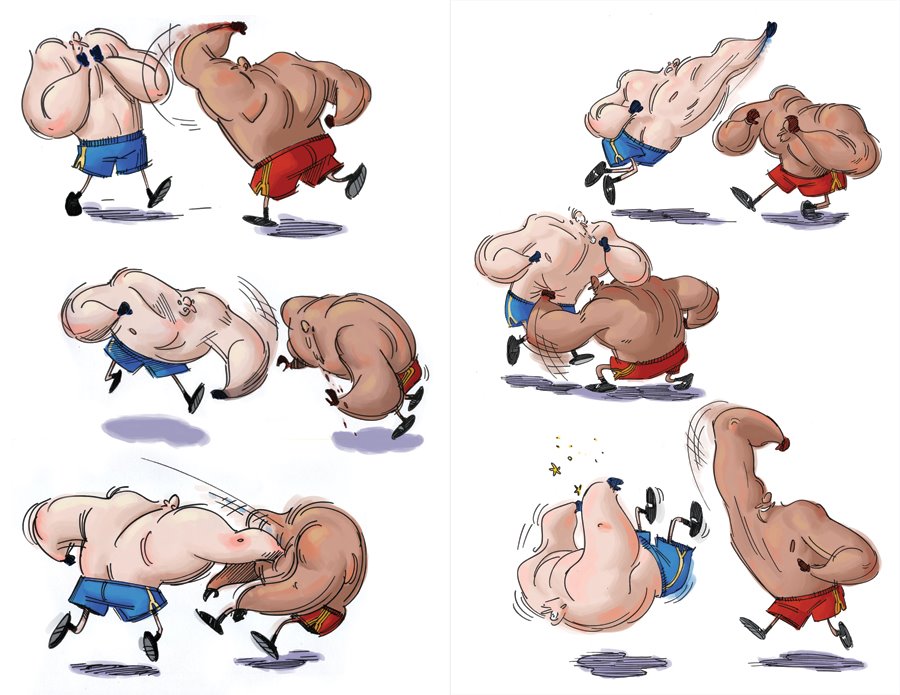
Here is the long awaited part 3 of my series on animating cut-out characters. I apologize for the delay. If you have not read Animating Cut-Out Characters - Part 1 or Animating Cut-Out Characters - Part 2 previously then I suggest that you do so before proceeding here. We are doing a pose to pose approach of keyframe animating a character walking. By pose to pose we mean that we layout important key boundary poses first, often referred to as extreme poses. Then we go back and fill in between those extreme key poses additional key poses, and then we go back and fill in more in between poses until we are satisfied with our animating of the walk. An alternate approach is to animate straight ahead which is how I did the walk for my Animating a Cut-Out Character in Toon Boom tutorial. Either approach is valid and useful and quite frankly a combination of the two approaches is more natural. Pose to pose sets up the basic animation and straight ahead is great for tweaking and smoothing. A question that often arises about the work flow of keyframe animation is "why do you not want the segments between keys to automatically be set to non-constant segments as you lay down the keys?" The answer is this is a personal choice and TBS is designed to work either way. I believe that tweening while setting keys interferes with my seeing the work evolve during flipping or onion skinning. Automatic tweens are defined by the keys on each end of the segment. So they don't really exist as a pose, they just reflect other poses which can be confusing. If we were hand animating we wouldn't see those final inbetweens while laying out our main poses so having automatic tweening turned off is just a more natural way to animate.Most of the instructions and the actual resulting movies are contained in the slide show so take your time, navigate using the Previous and Next arrows provided and backtrack through the slides as needed to follow along. As always, read the tutorial all the way through a couple of times and then do the work on your own as that is the only way to learn. Don't be afraid to experiment and expect to make a mistake or two as you go. We all learn from our mistakes, hopefully. I hope you enjoyed this tutorial series and learned some new skills. If you have questions or comments be sure to communicate them to me either at the Toon Boom Studio User Forums, The Discussion Area of The Cartooning In Toon Boom WIKI, or directly via e-mail or use the comments section here on the blog.
Labels: Cut-Out Animation, Key Framed Animation, Tutorial
Animating a Cut-Out Character in ToonBoom
This is the third part of our new tutorial series on creating and animating cut-out characters in ToonBoom Studio. If you haven't read Building a Cut-Out Character in ToonBoom or Rigging a Cut-Out Character in Toon Boom previously, I suggest that you do that before proceeding here.
Perhaps the most difficult aspect of this type of tutorial is the extensive complexity of the steps involved in performing key framed animation. I'm going to try my best to show you the most significant steps and to provide you with some helpful guides to assist your work. It isn't that difficult, but key framed animation is tedious and requires that you take your time and be very aware of what you are doing and how your are working. And just because you are not making individual drawings, key framed animation is still animating, so not only does it involve knowledge of using the software it also requires animating skills just the same as if you were hand drawing the animation. So you still have to deal with poses and timing etc. It takes practice, so let's get started.
I'm providing HERE a download of a SWF file that you can import into TBS to use as a pose guide for this animation. It will help you in positioning and posing the bird and in laying out the first thirty frames of the bird walking. So this first slide presentation will show you how to import the SWF into your project. If you download the ZIP file be sure to unzip it and remember where you put the walk0.swf file so that you can navigate to it in the file dialog when asked.
You can do that SWF import now or later when you are actually doing your animation. It is strictly provided as a aid to setting up the poses for the bird character. If you want to do your poses without using the guide that's a personal choice. I didn't have it when I did the animation myself, but then again I have done plenty of character walks in my career, so I just used my past experience to create the poses. In any case we will begin animating in the next slide presentation. My approach is to animate in multiple passes. So the first pass will be to get the basic walking animated and then in future passes we will refine the walk by adding movements of other body parts. Also I'm using what is termed as a straight ahead approach. Instead of doing certain key poses first and then doing inbetween poses, I'm doing each pose in sequence. You can key frame animate using either approach. I felt it would be easier to follow by showing the animating straight ahead style. The first pass roughed in walk
 Fig. 1 The timeline for our second pass of the walk where we animate the tail
After we have completed animating our rough walk in the first pass we are ready to go back through the timeline and make a second pass. This time we will just focus on animating the bird's tail feathers to add to our existing poses. We will leave "bird-P" expanded and we will just select the tail track label. Then we can step through the frames using the [S] key to move ahead to the next frame and the [A] key to move back to the previous frame. All animating is done using the scene transform tool (7). Remember in a walking motion the bird's rear end (tail feathers) will probably move up and down opposite the main weight shifting of the bird, sort of a counterbalancing motion. The second pass walk with the tail movement added
 Fig. 2 The timeline for our third pass of the walk where we animate the wingsAfter we have completed animating the tail movement in the second pass we are ready to go back through the timeline and make a third pass. This time we will just focus on animating the bird's right and left wings to add to our existing poses. We will leave "bird-P" expanded and we will just select the appropriate wing's track label. Then we can step through the frames using the [S] key to move ahead to the next frame and the [A] key to move back to the previous frame. All animating is done using the scene transform tool (7). The idea behind doing multiple passes is that it allows us to focus on small details. We are really trying to add some personality to the rough walk. Remember in a walking motion arms (wings) move counter directional to legs. The third pass of the walk with the wing movements added
 Fig. 3 The timeline with non-constant segments added between the keyframes.After we have completed animating our third pass we are ready to go back through the timeline and set non-constant segments between each keyframe on each element. This is just like having an assistant animator make inbetween drawings between each of our pose drawings. This "tweening" step adds a degree of smoothing to the walking movement. Many animators will stop after this step but it all depends on what you are trying to accomplish. All setting of non-constant segments is done with the scene transform tool (7) actively selected on the tool palette which insures that tweening is applied to all types of keyframe parameters. (location, scale, rotation, skew) The easiest way to make these tweening settings is to collapse the "bird-P" peg and set the segments between the keys on that main character peg letting the settings just reflect down to all the "hidden" children elements. The fully tweened version of the bird walking
That completes this installment in our series on building, rigging and animating a cut-out character in ToonBoom. In the next part of this series we will see how to remove the "tweening" and adjust and tweak the walk to make it even better.
Labels: Cut-Out Animation, Key Framed Animation, Tutorial
Rigging a Cut-Out Character in ToonBoom
This is the second part in our new tutorial series on creating and animating cut-out characters in Toon Boom Studio. If you have not read Building a Cut-Out Character in ToonBoom previously, then I suggest that you take time to do that now.
In the first part of this series we imported the black bird character into TBS. We outline the character using the drawing contour tool. Scaled the drawing to fit inside our 12 field guide. Then we cut out many of the bird's body parts and distributed them on to separate elements and then re-positioned them using our original drawing as a guide. We are almost finished with the cut-out phase of the building process, but we have a few more body parts to create before we can begin the rigging phase.
The previous slide show took us through creating the left wing and the left leg for the bird character. That completes the cutting out process for this tutorial series and we are ready for the next phase which is rigging the cut-out character for animating.
Note: You might be thinking " why not do additional parts for animating this bird like separating the pupil from the head so we can move it, or separating the lower beak so we can animate his mouth?" The answer is we certainly could have done that, but I chose not to because I wanted to leave you some future challenges for going off on your own when you finish the tutorial as presented. My goal is not just to show you step by step how I did something, but rather to inspire you to understand the steps so that you can expand that understanding to do your own work and to experiment with TBS further.
So let's get going with rigging this black bird. Rigging is a term used to describe the setting up of the control hierarchy of the cut-out character. It includes the ordering of the body part elements, the assigning of parent-child control relationships, some special 3D space adjustments of appropriate body parts, and the locating and setting of pivot points to provide more natural movements.That wasn't too dificult. We had to re-order some of our track layers and make some grouping selections and drag and drop labels to attach children elements to parent elements to create a control hierarchy. And we had to take advantage of 3D space to bump some body parts forward or backward in the display planes to compensate for changing the natural layering order of our track labels while constructing the hierarchy. Then we determined the locations of pivot points that would provide more natural movements when we start animating the bird. Of course the rigging does require some advanced planning and understanding of how we will be using the particular cut-out character. Things like breaking the character into two groups in the hierarchy to allow him to bend above the legs and positioning the wings so that when they move they don't get in front of or behind other body parts. It takes practice and experience to spot some of these potential issues and you, like me, will occasionally have to go back and adjust a rig design when you hit a problem during animation. That can be painful if you don't find it upfront before doing a lot of animating work, so I always try to test a rig by trying to make lots of poses with it for practice before I really start significant animating work.
Note: One sage observation on character design and rigging, don't assume that you can build an all inclusive layout or rig to cover every possible situation. Be prepared to build many rigs which are designed to address specific animating needs. Over complicating a rig to be all purpose makes animating more difficult and frankly never works as well as doing specialized separate rigs for specialized needs. Changes in points of view (profile, perspective, front, and back views) require separate cut-out character rigs so be prepared to build more than one rig for a character that you plan to animate extensively.
That concludes the second part of this series. We have taken a single drawing, cut it up into body parts, and constructed a hierarchically controllable rig for our cut-out character. Next time we will begin animating this bird character using key framed animation. Animating a Cut-Out Character in ToonBoom
Labels: Cut-Out Animation, Key Framed Animation, Tutorial
Building a Cut-Out Character In ToonBoom
This is the first part of a new tutorial series on creating and animating Cut-Out characters in ToonBoom Studio. Based on e-mails and comments which I have received as well as many postings on the Toon Boom User Forums, I have determined that there is a significant number of people who really want to see a detailed step by step tutorial style approach to this subject. I've written several previous tutorials on Photo Cut-Outs and Animating Cut-Outs and I hope that the lessons I have learned from doing that will help these next tutorials to be even better and more comprehensive.
NOTE: Thanks for all the comments and feedback and questions, they help me to better understand what works and what to improve in my communicating and presentation. So keep up your end too, and keep asking questions and making comments.
Just prior to this tutorial series, my most recent tutorial on Keyframing the Bouncing Ball was intended to isolate and simplify a complex subject. I hope that it has been helpful. One of the tools I introduced in that tutorial was the use of embeded slide show style step by step instructions. I'm expanding on that concept in this series. The slide shows serve two important needs. First they allow the presentation of significant amounts of information in a small footprint on the web page and secondly they allow the reader to move back and forth easily through complicated detailed instructional steps.
This series will follow the steps of constructing a cut-out character, rigging that character and animating that character. It will lay down, hopefully, a solid foundation for even more detailed tutorials expanding further into this subject. So let's begin a somewhat ambitious journey together. It all starts with a single drawing. 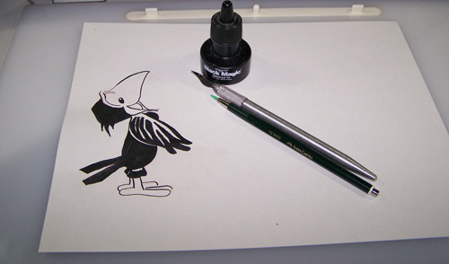 Fig. 1 A black bird character done with pen and ink
Above is a photo of the drawing on my drawing table. Yes, an actual hand drawn, old school, piece of cartoon art work. Does your cut-out character have to be drawn this way? No, you could draw it on your computer in some graphics software or even inside ToonBoom Studio itself. I wanted to do it this way for the instructional value so that we can explore the steps from scanning in a drawing to animating the character on that drawing.
I was looking at this drawing in my studio, it is part of a character design study on which I have been working. And while looking at it day after day for a period of time I realized it would really be fun to animate this black bird. So I scanned it into Photoshop and saved it as a GIF formatted image. I did absolutely no editing of the scan other than scanning it in at 300 DPI resolution. So you don't need Photoshop or any special software just draw your character and scan it into your computer to get it into an image file. (GIF, JPG, PNG etc.) I'm providing this image HERE as a download for you to use to follow this tutorial. By the way, read the tutorial and then re-read it and actually do it yourself. The only way to learn to animate in TBS is through doing it. And when you run into a problem and need help I'm here to respond to your questions on the ToonBoom User Forums or you can e-mail me directly or through the discussions area in the Cartooning in ToonBoom WIKI.
Let's get going with the first slide show. Use the Previous and Next arrows to navigate through the slides. They are packed with information so take your time and backtrack as often as you need.
If you navigated through the first slide show, you now have the bird character imported into your TBS project on a drawing element named "Scanned Image". The next slide show will take you through the steps to outline the character using the contour tool in drawing view. NOTE: If you prepared your drawn image in Photoshop with a totally transparent background and saved it as a PNG, you would not need to do the contour tool outlining steps. But I wanted to do the bulk of the work on this in TBS so I didn't do any special prep in Photoshop on purpose.If you read completely through that last slide show then you now have your character outlined using the contour tool and even scaled down to fit within your 12 field grid. Next we are going to make a duplicate of our character cell and begin the process of cutting out body parts and placing them into individual elements. The basic rule of cut-out design is "any part, that you want to be able to animate separately from any other part, must be placed on its own unique element."
If you have stuck with me this far, then you have taken your character drawing and imported it into TBS. You have outlined the character image with the contour tool and scaled the outlined character down in drawing view. Then you duplicated the cell that contained the outlined character so that you could cut parts out of that duplicate cell. You have cut out the head, right wing, right leg, the tail and the body of the bird and placed each part on to a seperate element. And then using the first cell of Scanned Image as a layout guide you have used the drawing select tool to re-position the cut-out body parts over your uncut outlined light gray character.
Note: One important tip in building a cut-out character is to have the character layout as close to identical in both drawing view and camera view. For this reason, be careful to avoid using the scene select tool (6) in the building process. Do all of your drawing object transformations (scaling/re-locations etc.) using the drawing select tool (1) even in camera view. That way when you finish building your character it will look the same in both views and more importantly it will be much easier to work with when you start using the character for animating. More on this later.
That's quite a bit. Next time we will create and add a few more body parts to the character and then build a hierarchal rig that will allow us to easily animate our cut-out character. Part 2 Rigging a Cut-Out Character in ToonBoom
Labels: Cut-Out Animation, Key Framed Animation, Tutorial
Keyframing The Bouncing Ball
In this tutorial, I am going to guide you through a step by step approach to creating a classical animation exercise, the bouncing ball, using the keyframe animation tools of Toon Boom Studio. Even if you're not really excited about creating this basic animation practice exercise, I hope you will find this tutorial very informative in that it uses a relatively simple animated action to demonstrate the very important and often misunderstood techniques of using keyframes and "tweening" without ending up with an action that looks like it was done by the software and not animated by a person. In other words I'm going to show you how to use "tweening" as a helpful step in the process and not have your work end up looking "tweeny".
If you are unfamiliar with the basics of key framed animation in Toon Boom Studio, before you continue here, I highly recommend that you take the time to read the 5 part series I previously wrote starting with Key Framed Animation Part 1 .
The tutorial will unfold as follow:
1. Creation of assets (cells) for a ball, a ground line, and a reference guide.
2. Switch to "camera view" and begin setting primary keys for the action.
3. Pass 1 refinements of inbetween frames converting some tweens to keys.
4. Pass 2 refinements of inbetween frames converting remaining tweens to keys.
5. Revising the spacing of the keys to improve the action.
6. Adding in squash and stretch to improve the action.
7. The final results.
 (fig. 1: Cell da-1)
We are going to start our bouncing ball animation by first creating a drawing element and creating one cell drawing in that element. We will name the element "da" and the one cell will be named da-1. This cell will be our ball. It is drawn in the center of the grid using the ELIPSE TOOL and filled with the PAINT TOOL. Once the ball is filled with color, you will want to select its outline and delete it so that all that is left is the inner paint filled zone in the shape of a ball. To get a perfectly round circle for your ball you can hold the "shift" key while drawing your circle. I actually just do mine visually because I prefer my ball not being exactly perfectly round.
 (fig. 2: Cell dc-1)
We can't animate a bouncing ball without a surface on which it will bounce, so next we need to create a second drawing element which will also have just a single cell drawing for the ground. It's basically just a thick black line, cell dc-1.
 (fig. 3: Cell db-1)
Now we are going to create another drawing element which also will have one cell drawing. This third drawing element, named "db", is going to act as a visual guide for our bouncing ball. Don't confuse this with a motion path or a motion guide. It is just a drawing of the path we want to use to describe the falling and bouncing of our ball. It is a visual animator's reference only and won't be included in the final animation movie.
With our three drawing elements created and our three cell drawings made, we are ready to switch from "drawing view" to "camera view" and start keyframing our bouncing ball action. The first thing you have to do is to decide on the amount of time you want to use to show this action. I set my example up using 32 frames for the bouncing action and I had to decide on which frames I would have the ball contact the ground and on which frames I would have the ball reach the top of its rebound. I created a simple timing diagram as a guide for my animating. Frames 1,12,21,and 28 are my top of the bounce rebound frames and frames 7,17,25, and 32 will be my ground contacts. One of the fun aspects of animating is that you can try your own ideas for timing your own action, so my choices are just that, my personal choices.
So now that you have your three drawing elements each containing a single cell at frame one, you will need to use the EXTEND EXPOSURE command to extend that one cell's exposure for each track out for 32 frames.
You will really only need to use one keyframing tool in this process. It will be the TRANSFORM tool, keyboard shortcut key (7). This is often referred to as the "universal" keyframing tool because it is used to set keys for location, rotation, scaling, and deformations. Any time you select an object with the TRANSFORM tool active you will see a selection bounding box with "hollow" un-filled grab handles. Any time you move, rotate, scale, or deform the selected object, using this TRANSFORM tool, TBS will automatically set or update the appropriate key framed values for the current frame. So for example if the current frame for the selected object is a "tweened" frame, it will be converted into a keyframe.
NOTE: Be careful not to use the SELECT tool (6) which has a bounding box that looks similar but has solid filled grab handles. The SELECT tool is not used for setting any keyframes, it is only used to set static scene level parameters. ( refer to Key Framed Animation for more details.)
AUTHOR'S NOTE: I have included five embedded interactive slide shows in this tutorial. You can follow the animation process by viewing them and navigating through their slides using the Next and Previous arrows in the upper left corner of the graphics. (fig. 4: Step by step slide show #1 )  (fig. 5)
Above is the timeline as it looks after you have set those eight initial key frames. Notice that there are connecting lines displayed between the keyframe markers. These connecting lines indicate that the segments between the keyframes are non-constant segments which is the same as saying that TBS will generate the inbetween frames which is referred to as "tweening". TBS can be set up to always create non-constant segments when you set keyframes or it can be set to always create constant segments and you will then manually have to designate when you want a connecting segment to be non-constant. I discussed this in the previous series on Key Framed Animation.
Above is the bouncing ball animation created with just the eight tweened keyframes. It leaves at lot to be desired, as you can see. The ball isn't following the arc guide but rather it is moving in a straight line from key position to key position. And it is moving at a constant velocity which means that the spacing between frames is exactly the same for all frames. (more on spacing later)
Your next steps in doing the bouncing ball are first pass refinements. You are going to select certain inbetween frames which are currently "tweened" and replace them with keyframes that better describe the path you want the ball to follow. One helpful hint at this point is to edit the color you used to make the ball and lower its opacity to about 33% which will make it appear transparent and make it easier to see through it to position it along your visual guide arc. When you finish all of your animating you can set the opacity back to 100% before publishing the final movie.
(fig. 6: Step by step slide show #2 ) (fig. 7)
Above is how your timeline will appear when you have finished your first pass refinement and added 7 more inbetween keyframes.
Next you are going to do a second pass refinement where you will convert the remaining 17 inbetween frames into keyframes. This will result in the ball bounce following your chosen guide arc exactly. It still has a constant velocity but we will address that soon.
(fig.8: Step by step slide show #3 )
 (fig. 9)
Above is how your timeline will look when you finish converting all the "tweened" inbetween frames into keyframes.
Above is the bouncing ball animation as created from our 2 revised keyframed passes. It is now following the guide arc nicely and we are now ready to refine the velocity of this action. To do that we will adjust the spacing between frames. The timing of the action is determined by the number of frames. But the changes in the speed of movement are adjusted by increasing or decreasing the amount of change between frames. We refer to this amount of change between frames as the spacing. The closer the spacing, the slower the speed of the movement appears. While the farther apart the spacing, the faster the movement appears. Forces in the physical world cause objects to accelerate and decelerate as opposed to just moving along at a constant velocity. Also in the case of a bouncing ball, the energy stored in the ball deceases after each ground contact which is visually seen by the decaying arcs between ground contacts.
(fig. 10: Step by step slide show #4)
Above is the animation of the bouncing ball after we have adjusted the spacing between the frames. It now bounces with a non constant velocity. It speeds up and it slows down as it moves down and back up etc.
We are almost done, but we still can improve on the bouncing ball by adding in squash and stretch. Squash and stretch are the natural deformations that the ball experiences due to external forces and things like gravity and the ground. The ball will compress or squash as it contacts the ground and it will elongate or stretch as it accelerates into a contact or out of a contact. One important trick associated with squash and stretch is that the volume of the object should be held constant even when deformed. The object does not shrink or expand it just deforms. (Really exaggerated animation does not always follow this guideline but that's just to produce a humorous cartoony effect.)
(fig. 11: Step by step slide show #5 )
 (fig. 12)
Above is how your timeline will look when you finish animating the bouncing ball animation. Notice that you will un-check the tracks for the guide arc and the spacing marks so that they are not included in the final movie. Also at this time you will want to return the opacity of the color of your ball to 100%.
Above is the final movie of the bouncing ball action. I added some extra frames at the end to allow for a slight roll to a stop from the last contact. You can play with the timing and the spacing of your own version of this bouncing ball and you can learn a lot from seeing the results of those experiments.
Hopefully you are beginning to understand how to use keyframing and tweening. First off, you should appreciate that you must decide the basic timing and spacing of any action. The software can help you to test out your ideas, but it can not really replace your skill or experience as the animator. If you set a few keys and "tween" the rest you will just get "tweeny" looking results. The best technique is to start with the basic tweened results and then step wise refine the action replacing the tweens with adjusted keyframes until you get a proper look to your work. Comments are always appreciated and I'll do my best to answer any of your questions here or on the TBS User Forums.
Labels: Key Framed Animation, Tutorial
Animating Cut-Out Characters - Part 2
In our last tutorial / article, Animating Cut-Out Characters - Part 1 , we learned how to copy a library template into our project and how to manipulate the character's arm to begin to pose the Little Boy. If you missed reading that article, now would be a good time to stop and do so.
For Part 2 in our series we are going to use the Toon Boom Studio supplied cut-out character Der Der. The Der Der cut-out was created and rigged in version 3.0 of TBS and there are some differences between its rig's appearance and usage and that of the Little Boy character. The major difference is that prior to version 3.5 there were no pegs integrated into drawing or image elements. Therefore each body part element was required to be attached to a parent peg element for keyframing. Later style rigs that take advantage of the integrated pegs are easier to use because you don't have as many tracks in the timeline, but also as we progress through this tutorial, I will point out other considerations.
We need to create a new project in TBS and set our animation properties for 24 FPS. I always try to animate at 24 FPS because it is an industry standard for timing and it is best to learn to time your animation work at a consistent frame rate.
We open the library and in the catalog list we go to the TOON BOOM TEMPLATES catalog and then to the CUT OUT CHARACTERS sub-catalog where we will find the DER DER RIG template. As we did in Part 1, we want to click and drag the template from the library to our SCENE 1 timeline. The template will be fully expanded when we copy in the template. Our first task will be to prepare the template for animating. So we need to collapse the character's master peg DER_DER_rig.
The Der Der character was created as an example of how to construct a cut-out character and the template has a number of features set up that we want to change because they are not the way we want to get started in animating this character. The first thing we will do is to go to frame 1 of the collapsed master peg and right click to open the context menu where we will select the SET CONSTANT SEGMENT option. We don't want tweens created yet while we are keyframing. Also if you don't have CREATE CONSTANT KEYFRAMES set up in your PREFERENCES do that now also. (explained in Part 1). Also go to your TOOLS menu and select the TURN PEG ONLY MODE ON option. Because we are doing pose to pose keyframing you do not want Snap Last Keyframe to be selected. (revised for V4.5) By now it should also go without saying that because we are key frame animating, you need to be in CAMERA (compositing) view.
Now we need to move the red frame slider to the last frame of our master peg, frame 20, and we will again right click to open the context menu and this time we select the REMOVE KEYFRAME option. Then we want to expand the master peg to see all the tracks in the timeline.
In this particular rig there are four drawing elements that have multiple cells set up for replacement animating. Left_pupil, Right_pupil, Eyes, and Mouth are those multi-cell elements. We want to set them all to just a single cell. So to do that we will adjust each of them one element at a time. Let's start with the mouth drawing element. by selecting all the frames from frame 2 to frame 20.
IMPORTANT NOTE: pegs are blue, drawing elements are green and pegs end with a -P identifier in their track name. As you will see shortly, great care needs to be observed to pay attention to which elements are pegs and which ones are drawing elements. We keyframe on pegs and we do replacement animation on drawing elements. (this is one of those old style rig VS new style rig considerations).
With the frames from 2 to 20 selected in the timeline for the mouth element, we look in the CELLS panel and see the current cell for frame 2 which is Mouth-b. Notice that the range of selected frames is showing as 2 thru 20. Even though there are other cells in some of those frames the CELLS panel displays only the first of the frame range's cell names.
Frame 1 has Mouth-a as its exposed cell, so we want to set the frames from 2 - 20 to also have Mouth-a for their exposed cell. We can type in the letter "a" in this case for the drawing or we can just move the cell swap selection slider until Mouth-a is the current selected cell.
We will repeat this process for the other multi-cell elements, Left_pupil, Right_pupil, and Eyes. Our goal is to have all of our drawing elements be the same element cell for all 20 frame exposures in our character rig.
You may have noticed that in my project's timeline there is an additional element named drA. As I said in Part 1 you still will often want to do some rough hand drawn animating as part of doing cut-out animating, particularly for the key poses. So I have a rough walk cycle with just the main key poses timed out in drA which we will use as a posing reference. You don't have to have this kind of reference but it helps.
Download drA as a compatible template for either Version 3.5 or Version 4.0. Open your library panel and import the downloaded template to your Global library using the context menu by right clicking in the catalog content pane and selecting IMPORT>IMPORT TEMPLATE FILE. Then you can drag a copy of the drA template to your project's timeline.
Looking in CAMERA view we see our character Der Der is not facing the same direction as our first pose in frame 1 nor is he the right scale size.
We will select the scene ops SELECT tool (6) and select the Der_Der_rig master peg in the timeline. Then we will look in the PROPERTIES panel where our selected peg's properties are displayed. These are static properties.
We will set the value of the second box for the Scale to negative which will flip the character horizontally. If you had set the value in the first Scale box to negative you would have flipped Der Der vertically. (This is a handy tip for changing an object's screen orientation, but be careful to remember that these are static properties and this is not how you flip characters if you wanted to do it dynamically through key framing. For that you would use the scene ops TRANSFORM tool (7) and not the PROPERTIES panel settings)
Now we have Der Der facing the correct direction but he is still too large so we need to scale him down to size. We are going to scale the entire rig and all its elements and not just for a single frame so we use the scene ops SELECT tool. We want to have the master peg Der_Der_rig selected and collapsed in the timeline. (Remember to watch for the solid bounding box handles for the SELECT tool and the hollow handles for the TRANSFORM tool ).
We will hold down the SHIFT key as we click and drag the upper right corner grab handle diagonally toward the center of the character to cause Der Der to get proportionally scaled smaller.
Once we finish scaling the character, we will click and drag him into position over the top of our hand drawn first pose reference where we can begin manipulating the rig to pose our character. To do that we will expand the master peg to make all of the rig's elements visible in the timeline. Then as we learned in Part 1, we will select the scene ops TRANSFORM tool (7) and use it to manipulate the character's body parts.
CAUTION: make sure that you only keyframe on the peg elements for Der Der and don't select the drawing elements by accident. If you forget and select a drawing element you will have to use UNDO to fix the mistake. Again, please note that this is an old style rig to new style rig, Version 3.0 to Version 3.5 and above consideration. Der Der's drawing elements don't have their rotational pivot points set for keyframing but because you are using V3.5 or V4.0 the drawing elements have integrated pegs and thus you can set keyframes in them which is not what you want to be doing for animating Der Der.
Be sure your red frame slider is positioned at frame 1. Which body part you choose to manipulate first is a personal choice. I typically start with the legs and work my way up to the arms. As we discussed in Part 1, you can move parts and then move other parts and just keep adjusting the pose until you are satisfied it is pretty much the way you want it. It doesn't have to be totally perfect as you can always come back later and adjust it as we will see in Part 3. When you finish manipulating Der Der into the first pose, collapse the master peg and with the scene ops TRANSFORM tool still selected use the keyboard short cut key " I " to set a keyframe. This locks down that pose for all elements in the rig from top to bottom.
Here is a great tip for using a reference drawing for setting poses for a cut-out character. In the properties panel for the drA element I have the element TYPE set to "background" which means that the element is visually behind all the "normal" type elements in Der Der's rig.
But to help see the reference more clearly while working you can go to the PROPERTIES panel and switch the drA element's TYPE to "foreground" which will pop it on top of Der Der. You can then switch the drA element's TYPE back and forth between "foreground" and "background" as you work to see it better or get it out of your way as needed.
With our frame 1 pose finished we are ready to do a second pose. We are going to animate Der Der using the pose to pose technique. When animating a walk cycle I do the contact poses first. So our second pose is at frame 16 and is the repeat of the first pose except that it is in a different location on the screen. Before we can create this pose we need to add a parent peg to the Der Der character for the purpose of animating his forward motion. We want to separate the forward motion from the actual walk cycle motion so that we can reuse the walk cycle itself later in other scenes or projects.
We will collapse the master peg for the Der Der character and select it in the timeline. We then click on the icon for adding a parent peg. (see the photo above)
Once the new parent peg is added to the Der Der character we want to rename it to forward-P. We will only be keyframing Der Der's foward motion on this peg while all his walking motions will be keyframes on his character rig pegs. So with the forward-P peg expanded and selected and the Der_Der_rig peg collapsed, but visible, we will select the scene ops MOTION tool (0) and move the red frame slider to frame 1 and press the keyboard short cut key " I " to set a motion keyframe. Then we move the red frame slider to frame 16 and set a second motion keyframe.
At frame 16 we see the position of our second pose. We still have the forward-P peg selected and the MOTION tool is still selected. We click and drag the Der Der character while holding down the SHIFT key to constrain his up and down position until the character is on top of our reference pose. You could also have used SHIFT plus the RIGHT ARROW key to make this move.
When you have the pose lined up over the reference pose, select the collapsed Der_Der_rig peg, and select the TRANSFORM tool (7) and using the context menu or the keyboard short cut key " I " set a keyframe at frame 16 to lock down the pose. Don't forget to do this because if you do forget and start changing keyframes down stream on any previous frame, they will effect frame 16's pose.
We are ready to do the middle contact pose for our walk cycle which is on frame 9. So we select the MOTION tool (0) and we select the forward-P peg and move the red frame slider to frame 9 and using the context menu or the keyboard short cut key " I " set a new motion keyframe at frame 9. Then we use the SHIFT key and click and drag the character into position over our reference pose.
The character's pose is not correct for the middle contact position so we need to re-pose Der Der to match the reference pose.
We do this exactly like we did for the first pose using the TRANSFORM tool to adjust the body parts for Der Der. Remember to be careful and only keyframe on the peg elements and not on the drawing elements of Der Der's rig.
 So at this point if we turn on ONION SKINNING we can see the first two poses which are opposite contact poses. And we can also see the second and third pose which are also opposite contact poses.
  Our next steps will be to create the three poses between frame 1 and frame 9 as seen by our reference drawings above.
  And we also need to create the three poses between frame 9 and frame 16. So that's where we will pick up in Animating Cut-Out Characters - Part 3. We will also then begin doing the additional in between poses to smooth out our character's walk.
 Labels: Cut-Out Animation, Key Framed Animation, Tutorial
Animating Cut-Out Characters - Part 1
Introduction
This is the first in a series of tutorials about creating and animating “cut-out” characters. I’m going to try my best to be as in-depth as practical, so be patient, as my goal is to provide a definitive series on “cut-outs”. I plan to balance basic conceptual understanding of the subject with step by step “how to” guidance.
Initial Concepts
First, I want to clearly define what I mean by a “cut-out” character. A “cut-out” character is a character that has a multi-element hierarchy to create movable joints. Additionally a "cut-out" character will consist of replacement parts that can be swapped. Thus with the "cut-out" character we will combine articulation of jointed body parts with the replacement of body parts to create the illusion of movement.
In creating a hand drawn cartoon character we must consider how we will be animating that character. There are two fundamental approaches to producing hand drawn cartoon animation. There is the “full” animation approach and the “limited” animation approach. The “full” animation approach is to redraw the full character in its entirety for each frame that changes as we create the illusion of movement. The classical “limited” animation approach is to separate the character into layers and only redraw those layered parts that change in a frame while "holding" the unchanged layers. A common misconception is that the “limited” approach is a less skilled approach to animating then using the “full” approach. This actually is not the case. It requires every bit as much animating knowledge and skill to do classical “limited” animation, but it can reduce the amount of labor required to produce the final animation by reducing the amount of drawing needed. So the “limited” part has to do with drawing efficiency.
“Cut-out” animation in Toon Boom Studio is based on the “limited” animation approach and can be used to produce animation with even less drawing needed than classical “limited” animation. But again there is a common misconception that it requires less animating skills than fully drawn animation. It may not require as many drawing skills but it requires significant animating skills just the same. And even though it requires less drawing skills it requires even more skills in the areas of planning, construction and software usage. So don’t assume just because you are substituting a cut-out character for a fully drawn character that it is easier to implement. Successful cut-out animation is a highly skilled approach to animation production. Cut-out animating is not less skilled animation, it just uses different skills and places different emphasis on the animator’s skill sets.
For our purposes in this series we are primarily focused on “cut-out” characters to implement a form of “limited” animation. Where possible we will look at creating posable and animatible digital puppets, but at the same time we will also talk about replacement animation and the planning and reuse of drawing assets. Certainly there are styles of characters that lend themselves to more puppet-like construction and other styles of characters that really don't. Depending on the character style we may need to use a combination of both techniques. In fact, if you are familiar with stop motion animation techniques, you will realize that we are going to really end up designing our characters to be a jointed articulated puppet and we will also want to use replacement pieces for different character parts as well. Our goal is to produce the illusion of movement and we will do that sometimes using articulated joints to produce changes between images and other times we will change the drawing itself for certain body parts.
Getting Started
A sequential approach to working with cut-out characters might be:
1. Establishing a character concept.
2. Selecting design options based on the character's expected performance requirements. (performance is a theatrical term associated with acting)
3. Drawing a series of character poses and views.
4. Cutting the character up into parts.
5. Laying out the character parts in elements.
6. Rigging the character for animating.
7. Testing and Enhancing the character rig.
8. Animating the cut-out character.
But sometimes learning and mastering a complicated new technique isn't easiest when approached along the ultimate sequential work flow. A common mistake by new cartoon makers is to start trying to create and construct a cut-out character before they have a fundamental foundation in cut-out animating technique. We actually want to start at the end of the work flow, animating the cut-out character, and then we will work our way back to the creation of our own cut-out characters.
The Rigged Cut-Out Character
We will start by opening a new project in TBS and opening the library view panel. The library is divided into catalogs and those catalogs are divided into sub-catalogs. We want to go to the Toon Boom Templates catalog and find the sub-catalog named Cut-Out Characters. Inside that sub-catalog there are two character rigs. We will be using the character named Little Boy. (note: the Little Boy character is included in TBS version 4, if you don't have version 4 yet, then you can follow along using the Der Der character from version 3.5. The fundamentals are the same, and I will be careful to point out any variations in technique created by software usage changes.)
 If for some reason you don't have a Toon Boom Templates catalog in your TBS library, you can get this catalog by just right clicking in the catalog listing pane to open the context menu and select the menu option to Reload Default Templates. That will restore the factory set default templates while not disturbing your other library catalogs or assets.
In order to use the Little boy character we need to click on his template in the library panel and drag it to our scene 1 time line. You want to drag the template label across to the time line track label pane and drop it at the top of the track label list. (You will see a "plus" icon (+) displayed when it is OK to drop the dragged template.) When we release the mouse button at the end of our drag we see the character's hierarchy of elements displayed in the time line track label list.

If you are not familiar with the time line and how it displays a hierarchy of elements, then this is a good time to spend a few minutes getting acquainted with it. Elements can be connected into hierarchical relationships where their behavior is controlled by their location in the hierarchy. Elements can be parents of other elements or children of other elements or they can be siblings (brothers or sisters) of other elements. A child element is influenced by its parent, a parent element is not influenced by its children. Siblings stay together based on the influence of their common parent. As we proceed, these relationships and their interactions will become obvious. The character hierarchy can be collapsed or expanded as needed and we will explore the advantages of doing both as we progress. For the moment we will fully expand the character's hierarchy to allow us to discuss some aspects of cut-out characters in general.
People and other animals are jointed. In fact the whole nature of articulated movement is based on joints, and even the fact that certain joints operate differently from other joints. Your shoulder joints, for example, have a different range of motion from your elbows, and your hip joints have a different range of motion from your knee joints etc. So, thinking about of how to construct a cartoon character to have articulated body parts and joints is to mirror nature.
If we go back and look at early cartoon character designs in the 1920’s and 1930’s they were actually very unnatural and based on “rubber” hose style limbs. That wasn’t an aesthetic choice as much as it was a practical design choice because those style limbs are much easier to animate than anatomically correct limbs. Disney artists in their efforts to create a more natural and realistic brand of cartoons quickly abandoned the “rubber” hoses in their characters. (Except in the case of Mickey Mouse, who was and to some extent still is drawn with "rubber" hose limbs.) Observations of natural organic movements quickly reveal that they are based on expansions and contractions of muscles under the character’s skin. Those observations made during the 1930s by Disney artists were the beginning of the application of squash and stretch in character animation. The character’s bones and joints provide the support structure as well as impose limitations on movement while muscular actions contort the shapes of body parts. “Full” animation captures these muscular expansions and contractions, while “limited” animation usually abbreviates them and often just ignores them for the most part for the sake of production efficiency.
Jointed characters have to be planned around their natural breaks. These natural breaks are how we subdivide the character into component parts and they usually fall on actual joints like shoulders, elbows, knees, ankles, hips, neck ect. Breaks are points of articulation but they shouldn’t be visually obvious. If you don't want your characters to look like hinged “cut-outs” then you need to plan and design with break camouflage in mind. (We will explore breaks and joint construction in future parts of this series)
The whole foundation of limited animation is based on holding the position of some body parts while changing the position of other body parts. This means we will want to separate our character into multiple parts and then each of those parts can then be held or changed as desired to produce the movement. So certainly the degree of granularity, that we decide to use to subdivide our character, is going to be a primary design decision. The more granular the subdivision, the more parts into which we will have to separate the character and potentially the more flexibility we will have in moving the character. But with greater flexibility comes greater complexity, more parts to account for in our animating, so we will have to weigh the cost of the flexibility we might gain against the extra work involved in managing a more complex character. Any body part that will need to be animated independently of all other body parts should be separated on to its own element layer. But we must evaluate which body parts truly need to be independent to satisfy our animating needs because that produces increased complexity. One part of that evaluation is the trade off between producing motion through articulation, the physical repositioning of body parts, and producing motion through drawing replacement. In many cases it isn’t always one way versus the other but actually a balanced combination of using both methods based on how we want to implement a movement. (We will get more into this discussion in future parts of this series.)
For now you should just look at the granular division of the Little Boy character and make note of how he has been constructed. Characteristic of cut-out characters he has a top parent peg element called the character's main peg or master peg. Then he has subdivisions of an upper and lower body, usually called torso and hips. Then these subdivisions are further divided into logical articulation chains. Notice the parents, their children and the various siblings in this character's hierarchy. (Again, there will be more discussion of this in future parts of this series)
It's time to get started animating the Little Boy, so we need to make a few settings to assist us while we work. The template has some "tweening" included that we don't want at the moment. So we need to remove any non-constant segments. (If you are not up to speed on keyframed animation I highly suggest that you read Keyframed Animation Part 1 through Part 5 to insure you have a solid foundation before proceeding.) We want to select the scene operations transform tool and make it active and make sure your main view panel is set into camera view. Keyframing is always done exclusively in camera view and never uses drawing view. We start off by collapsing the character's master peg. Remember that when a parent peg is collapsed it not only hides its children's track labels, it also causes any actions that we apply to the parent also to be applied down to all its children. We select the collapsed master peg track and move the red frame location slider to frame 1 and we right click to open the context menu and select the menu option Set Constant Segment. The lines in the time line track that were connecting the first and last key frame in the keyframe pair are no longer showing which indicates that this is now a constant segment and if we expand the master peg, we will see this is now true for all its children tracks.
We also want to go to Preferences and make sure that we have checked the boxes shown in the above picture of the Scene Planning tab, particularly the Create Constant Keyframes setting. When working with animating a cut-out character it is best to not have TBS automatically create non-constant segments between keyframe pairs. We want to set all our segments individually as we animate them. So the default should be for no "tweening" which means constant segments.
 One more setting before we get going. We need to select the Turn Peg-Only Mode On (M) menu option under the Tools menu. This is a visual aid that helps us to not mistakenly select drawing objects when we are wanting to select pegs in camera view.

Cut-out character animating is done by posing the character in each frame using the scene operations tools, mostly the Transform tool (7). Notice that the Transform tool bounding box and the Select tool (6) bounding box look very similar in camera view. Visually the difference is that the grab handles are unfilled squares for the Transform tool and filled squares for the Select tool. Learn this distinction well as it will save you much grief in the future. These tools are very different in purpose and usage so don't be fooled by their similar displays. The Select tool is used to set "element" level parameters. The transform tool is used to set "frame" level parameters. As a general rule, you never want to change element level parameters once you start keyframe animating. Changes in element level parameters after you start keyframing can totally and unexpectedly alter all of your animation work and can be disastrous. Your only clue that you have the wrong tool selected is those filled grab handle squares. If your animating and see them, they are shouting to you "stop!! danger do not proceed!!".
Before we start animating the Little Boy we might want to observe how his rotational pivot points have been preset. As part of the rigging of this character the designer used the Rotation tool (8) to position the "green" circle for each part and hierarchical grouping so that they would rotate around that point to insure more natural movement. Because this is an already rigged character, we will not need to worry about setting these pivot point locations. But it is important to note that rotational pivot point locations are "element" level settings and just like my previous warning about not changing "element" level settings after you start keyframe animating, don't change the location of rotational pivot points after you start keyframe animating, as the results can be unexpected and disastrous. If for any reason you need to use a different pivot point while keyframe animating, you can move the "blue" circle pivot point that is showing with the Transform tool bounding box. That pivot point is temporary and will only effect the transform setting as long as the current transform selection is active. Again this is a very important distinction that you should learn early or you will experience the consequences.
The template came set with eight frames so we want to extend the timeline out to twenty frames just to give ourselves some additional animating room. With the character's master peg collapsed and selected we move the red frame location slider to frame twenty and right click to show the context menu and select the menu option Extend Children Exposure... (this is a new command in version 4.)
We also want to go back to frame 8 and select Remove Keyframe to get rid of that last keyframe that was also part of the template. Don't worry about making changes to a template once you drag it into your project time line. The original template in the library is not linked and therefore will not be changed in any way. (Warning: don't select Remove All Keyframes as that would be disasterous and totally destroy the character's rigging settings. Aren't you glad I'm pointing out the mines in this mine field before you get "blown" up.)
Finally we can start animating. So we will begin with a first pose for the Little Boy character. This is the natural pose of the template so we will just use it for our first pose in this example movement. We are going to animate the character's left arm. Our first pose is at frame 1 so there is nothing to change on frame one.
 We will set our second pose for this example at frame 8. So move the red frame location slider to frame 8. Double check that you have the Transform tool selected as the active tool. Watch for those unfilled squares on the bounding box. Now you can visually try to select the character's left arm in camera view or you can select the track label in the time line track label list. I prefer the track label selection approach as it is easier most of the time. We want to select the track labeled "little_boy_l_up_arm".
You need to get use to being very focused and aware of your actions when animating a cut-out character. Before you move the character, always be sure you are working on the frame you want, always be sure the correct scene operations tool is selected and active, and always be sure you are setting keyframes on the element track that you want. This is a very important aspect of cut-out animation to understand, know where you are, what you are changing and how you are changing it before you change anything. And take your time, rushing causes mistakes and mistakes can multiply and get out of control quickly. ( I will try to show you how to undo most mistakes when you realize you have made them in a future part of this series, but fixing mistakes can waste a lot of time so it's better to move carefully and minimize the careless mistakes.)
Notice that in camera view once we select the track label, the character's left arm is highlighted by the Transform tool's bounding box. We can rotate the arm by using the bounding box's rotate handle and dragging it counter clockwise to raise the shoulder. (note: that a change in version 4 now allows us to rotate the transformed object from any of its corners and not just using the rotation handle. In version 3.5 you still need to use the rotation handle.)
 That repositioned the boys shoulder and upper arm, but we also want to move his lower arm position. Notice that because the lower arm and hand are children of the upper arm that they moved with the upper arm. But we have the ability to move them individually as well. There relationship to the upper arm is enforced as part of the relational hierarchy. So now we select the track labeled "little_boy_l_arm". This will let us just move the left lower arm and its child, the left hand.
 As you can see we can bend the arm naturally because of the way the character has been constructed and rigged. It is important that you begin to see that we are fundamentally posing a puppet. We can move the various body parts one at a time to get just the pose we want. Sometimes we will move a part like the upper arm, then we will move the lower arm and decide that the upper arm position needs to be re adjusted. This kind of iterative back and forth adjustment of parts is typical of posing a cut-out character.
We can select and adjust the position of the left hand the same as we did the left upper arm and the left lower arm.
So now we have two poses for the Little Boy character. We are only focusing on his left arm to keep this example simple. His arm is positioned in pose one on frame 1 and is positioned in pose two on frame 8. If we looked at the animation at this point the arm would appear to "jump" between poses abruptly. So we want to smooth out the motion by adding incremental inbetween poses at frames 2,3,4,5,6,and 7. We could do these by hand just like pose one and pose two, but there is an easier way to proceed. We can use "tweening". We can select all the tracks for the Little Boy's left arm, move the red frame location slider to frame 1 and use the context menu option Set Non Constant Segment. This will generate the inbetween arm positions. The tracks show the line displayed between keyframes to indicate a non-constant segment.
 The picture below shows you the character poses. The two poses I set, and the six poses that TBS generated to inbetween my two poses. Now computer generated inbetween poses are a great time saver but they are usually just a starting point and most animators will fine tune and adjust those poses manually. ( In a future part of this series we will see how to fine tune and adjust the inbetweens generated by TBS.)
  Click on the picture to see an enlarged version
The last thing we want to look at in this first part of the Cut-Out series is the replacement parts included in this template. They are for the mouth and the eye brows. We aren't going to do any swapping of parts yet but I wanted to point them out for you to notice and study before we get to Part 2.
 We have covered many fundamentals in Part 1 and we have learned basic rig manipulation to set a partial pose with the character. Next time we will learn to animate a full sequence of motions. Animating Cut-Out Characters - Part 2
Labels: Cut-Out Animation, Key Framed Animation, Tutorial